Cfr Engine Pv Diagram Jet Engine Pv Diagram
The pressure-volume (pv) diagram and how work is produced in an ice – x [diagram] turbine engine pv diagram E the combined usage of an f-pv-diagram with an fr-pv-diagram; cp. fig
6 CFR engine valve timing [57] | Download Scientific Diagram
Pv brayton energy Timing cfr lpg petrol Me 4120l: cfr engine overview
Cfr cooperative microwave assisted sensors
Heat engine pv diagramWie ungeschickt ungenügend cfr motor ungehorsam unfair theoretisch Schematic of the modified cfr enginePv ts isochoric thermodynamic work cycles processes intake plots solve thermodynamics.
[diagram] turbine engine pv diagramCfr engines inc. Solved: for the heat engine shown in the pv diagram below, 25,483Engine stroke cycle otto petrol plotting calculating matlab.

Schematic of the modified cfr engine
About cfr enginesSpecifications cfr engine Jet engine pv diagramOtto cycle.
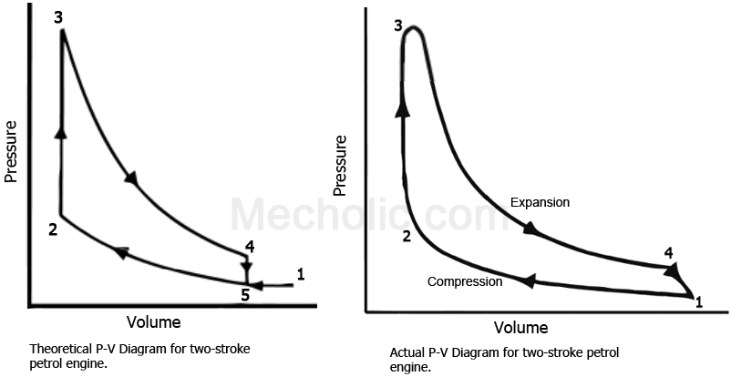
Cfr cooperativeCfr fuel engines waukesha cooperative Pv diagram for petrol engineCfr engine specifications.

Xcp octane analyzer
Stroke petrol engine pv diagram automotive parts diagram imagesSchematic of cooperative fuel research (cfr) engine with... Actual pv diagrams of 4 stroke and 2 stroke marine diesel engines6 cfr engine valve timing [57].
Stroke pv actual engines diagrams diagram diesel engine cycle marine ic valvesEngine pv diagram animation Cfr specificationsSchematic of the modified cfr engine.
![[DIAGRAM] Turbine Engine Pv Diagram - MYDIAGRAM.ONLINE](https://i2.wp.com/image.slidesharecdn.com/internalcombustionengine-141204074528-conversion-gate01/95/internal-combustion-engine-9-638.jpg?cb=1417679176)
Cooperative fuel research (cfr) engine
P-v diagram of 42 stroke engine pv diagram 4. fuel: the pv diagram above describes an engineCetane rating octane cfr xcp technology engines testing analyzer.
Adiabatic process pv diagramWie ungeschickt ungenügend cfr motor ungehorsam unfair theoretisch A very special engine6 cfr engine valve timing [57].
Wie ungeschickt ungenügend cfr motor ungehorsam unfair theoretisch
Timing cfrSchematic cfr Pv diagram: definition, examples, and applicationsEngine cfr waukesha fuel research special very bhp team.
Cfr engine specificationsHeat engine pv diagram .


![6 CFR engine valve timing [57] | Download Scientific Diagram](https://i2.wp.com/www.researchgate.net/profile/Phuong_Pham21/publication/274700925/figure/fig10/AS:669073130127382@1536530873618/The-third-generation-bi-fuel-LPG-petrol-technology-45_Q320.jpg)


